The goal is to build a groovebox using the last Arduino : Arduino Due.
The processor is a 32 bit ARM3 cadenced at 84 MHz, and it has a Digital-to-analog output.
http://arduino.cc/en/Main/ArduinoBoardDue
It can easily generate sound at 44 kHz. The DAC is 12 bits. It's a little less than nowadays audio products, but it corresponds to 80-90's products like first yamaha or akai samplers. The sound is a little more "compressed", but still used in modern music.
The FatLib library gives Arduino quick access to SD card. It's quick enough to read samples. So the groovebox will have a sampling part, to generate beats from one-shot samples, and a synth part, to generate bass, chords and leads.
I could start this project by inspiring on RCArduino Blog, by Duane B. (a very good blog on arduino), and this particular post :
http://rcarduino.blogspot.com/2012/12/arduino-due-dds-part-1-sinewaves-and.html
Here are some demo of what is possible to do with groovuino. (it's just a proof of concept, not a very musical song) :
http://groovuino.blogspot.fr/2013/05/groovuino-groove-box-demo.html
https://soundcloud.com/gaetino/groovuino
Here are the specs of groovuino groovebox :
http://groovuino.blogspot.com/2013/04/main-functionalities.html
And here some simple examples to start programming with groovuino library :
Mono synth : http://groovuino.blogspot.fr/2013/04/build-groove-box-with-arduino-due-post3.html
Mono sampler : http://groovuino.blogspot.fr/2013/04/lets-code-simple-sampler.html
Polyphonic sampler : http://groovuino.blogspot.fr/2013/06/polyphonic-sampler.html
First of all, let's make a C++ library with main objects like sampler, oscillators, filters,...
I opened a guithub project :
https://github.com/Gaetino/Groovuino
Let's quickly explain the library files :
(you can have a look here :
http://playground.arduino.cc/Learning/SDMMC
http://arduino-info.wikispaces.com/SD-Cards )
If you include sampler.h, make sure you have previously imported SdFat.h in your main program.
First, I define a structure corresponding to the header of a wave file : "wave_header".
Then I create a sampler class. Through this class, you can load and read a wave file byte by byte.
In your main program, you will have to create a loop called 44000 times per second. I will call it the 44 kHz loop. You can do this by defining a timer. See timer.h file.
Methods :
- init()
Initialize data. Must be called in setup() function of main program.
- splay(volume, note)
Sampler play. Start to play the sample previously loaded, with a certain volume and pitch. (note that pitch is not coded yet)
- load(samplename)
Loads the sample file (must be a .wav file). It can read mono or stereo file (a stereo will be transformed to mono), at 44 kHz and 16 bit. The wave header is read, and all data is loaded in the structure.
- sstop()
Sample stop. Just stop the reading of the sample.
- notestop(note)
Stops the sample corresponding to a certain note, and start the decreasing of the sample volume (because of certain samples which do not end on a 0 volume, I had to make a little decreasing enveloppe to the end of the sample reading, to put the volume to 0 without earing a "click").
- setVol(volume)
Set the volume of the sample.
- buffill()
Loads the buffer data, with wave data. The buffer value is actually 1024, you can adjust it to what you want. (data "bufsize").
This function must be called at very high rate, in a different loop than the one which is playing the file (a timer, or main loop). There is 2 buffers. One is being played by output() function, and the other must be loaded prevently. If it has not been loaded yet, the function loads this buffer while the other is being played.
- next()
Prepares the index of the buffer to be read. Must be called just before output() function, in the 44kHz loop.
- output()
Returns a 12 bit integer corresponding on the sample played. Must be called in the 44 kHz loop.
It will be based on reading a wavetable. For now, I just defined some basic wavetables in the memory of Arduino. But later, we will be able to load any wavetable from SD card. It should be a wave file with 600 samples.
You must play the osc in the 44 kHz loop.
Methods :
- init()
Initialize data. Must be called in setup() function of main program.
- setNote(note, volume)
Set the note and volume of the oscillator (for example data coming from MIDI NoteOn)
The note is corresponding to normalized MIDI data :
If the glide function is activated, the frenquency will be incremented or decremented little by little until reaching the new note.
- stop()
Indicates that the osc is no more playing (correponds to MIDI NoteOff). Even if it's the enveloppe which stops the sound of the osc (and not the method stop()), it's important to call it, to indicate to other methods that the sound is no more playing. Important for the glide, for example.
- setVolOsc(osc number, volume)
Set the volume of the chosen oscillator.
- setWavform(osc number, waveform number)
Set the waveform of the chosen oscillator.
For now, I just put 5 waveforms, but the goal will be to choose waveform files from the SD card.
- setFine(osc number, fine tune)
Set the fine tuning of the chosen oscillator.
Fine tuning will be between -0.5 to +0.5 pitch
- setGlideTime(glide time)
Set the glide time in milliseconds. (1 to 1280)
- next()
Prepares the index of the buffer to be read. Must be called just before output() function, in the 44kHz loop. Increments or decrements the glide if necessary.
- output()
Returns a 12 bit integer corresponding to the sample of waveform playing. Must be called in the 44 kHz loop.
Contains methods to initialize timers.
See here the discussion about timers on Arduino Due :
http://arduino.cc/forum/index.php?topic=130423.0
- startTimer(Tc, channel, irq, frequency)
Start the timer on a chosen channel and irq, at a defined frequency in Hz.
- setFrequency(Tc, channel, frequency)
Update the frequency of the timer, the frequency is in Hz.
- setTimerBPM()
Set the timer frequency, calculating it from general bpm.
This class defines an ADSR enveloppe. The data out will be a volume which you'll have to multiply to the sound you want to control (oscillator or sample).
- init()
Initialize data. Must be called in setup() function of main program.
For the first program design, we won't care about effects (filter, chorus, etc...). Let's make simple.
The groove box will first have a 3-osc mono synth and a 3 polyphony sampler.
Here is the schema:

Let's make a pannel. This one is not good, but it's enough to test ergonomy :

Be careful that nothing is sent to Arduino by a MIDI controller when loading the firmware in the Due.
Here are the schematics from MIDI Breakout board nicely published by Sparkfun. I used these to make my own board. (Or you can buy the board to Sparkfun) :
MIDI IN :

MIDI OUT :

See :
https://www.sparkfun.com/datasheets/BreakoutBoards/BOB-09598-MIDI_Breakout-v11.pdf
Digital IN :
Have to read 12 buttons values :
4 "MODE" buttons
8 "STEP" buttons
Connections are arduino basics. Digital pins are connected like this :
http://arduino.cc/en/Tutorial/DigitalReadSerial
You can connect them to pins 22-30 for exemple.
Digital OUT :
If you have 3.3V LED, you can connect them directly between digital pins and ground. If not, don't forget to add a resistor.
Have to read 4 potentiometers, and 3 sensors.
Like digital, connections are arduino classics :
http://arduino.cc/en/Tutorial/AnalogReadSerial
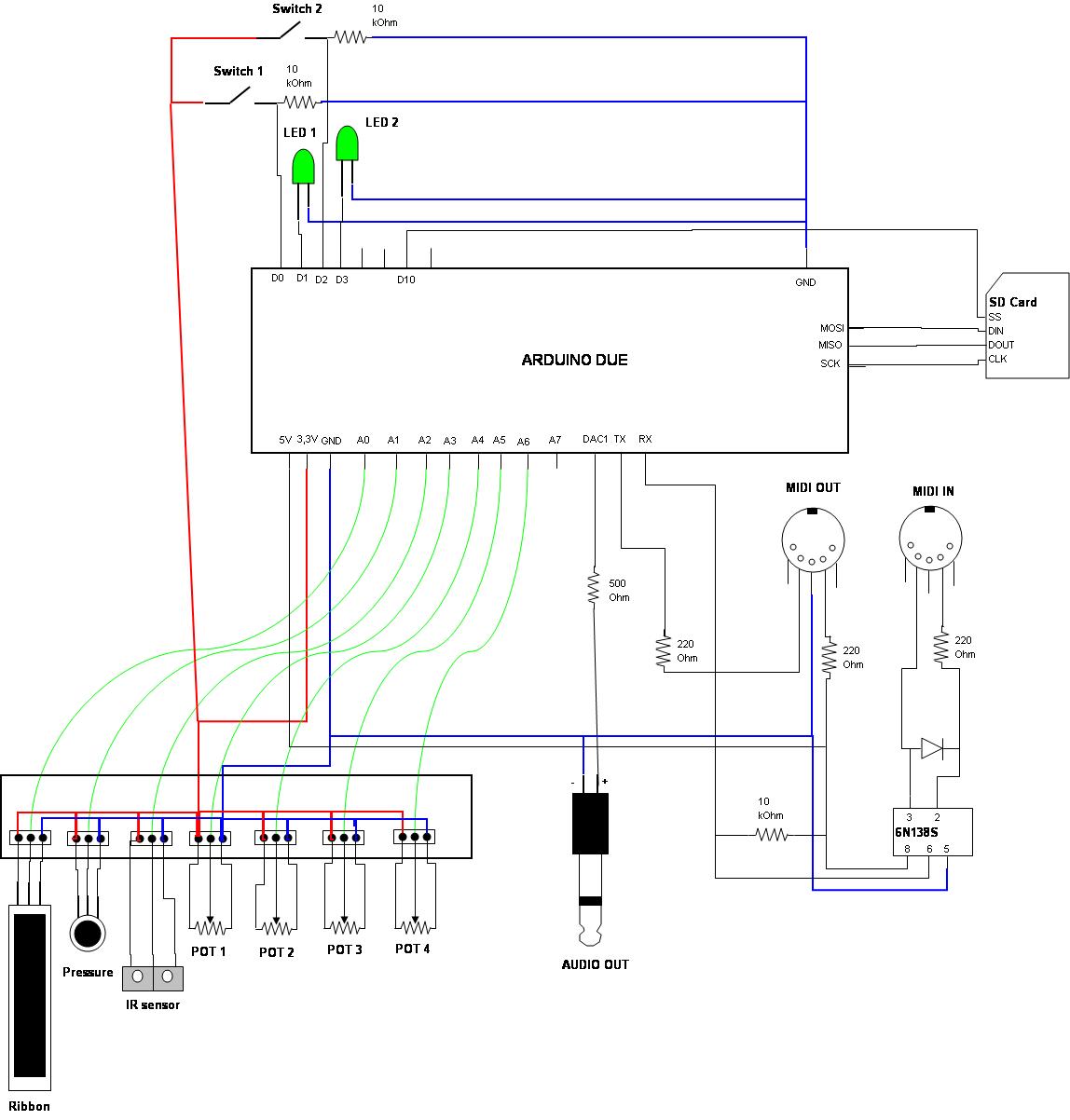 I represented only switch 1 and 2, and LED1 and 2, but there is 12 switches and 12 LED (8 step buttons, 4 mode buttons).
To be continued...
The processor is a 32 bit ARM3 cadenced at 84 MHz, and it has a Digital-to-analog output.
http://arduino.cc/en/Main/ArduinoBoardDue
It can easily generate sound at 44 kHz. The DAC is 12 bits. It's a little less than nowadays audio products, but it corresponds to 80-90's products like first yamaha or akai samplers. The sound is a little more "compressed", but still used in modern music.
The FatLib library gives Arduino quick access to SD card. It's quick enough to read samples. So the groovebox will have a sampling part, to generate beats from one-shot samples, and a synth part, to generate bass, chords and leads.
I could start this project by inspiring on RCArduino Blog, by Duane B. (a very good blog on arduino), and this particular post :
http://rcarduino.blogspot.com/2012/12/arduino-due-dds-part-1-sinewaves-and.html
Here are some demo of what is possible to do with groovuino. (it's just a proof of concept, not a very musical song) :
http://groovuino.blogspot.fr/2013/05/groovuino-groove-box-demo.html
https://soundcloud.com/gaetino/groovuino
Here are the specs of groovuino groovebox :
http://groovuino.blogspot.com/2013/04/main-functionalities.html
And here some simple examples to start programming with groovuino library :
Mono synth : http://groovuino.blogspot.fr/2013/04/build-groove-box-with-arduino-due-post3.html
Mono sampler : http://groovuino.blogspot.fr/2013/04/lets-code-simple-sampler.html
Polyphonic sampler : http://groovuino.blogspot.fr/2013/06/polyphonic-sampler.html
Software
First of all, let's make a C++ library with main objects like sampler, oscillators, filters,...
I opened a guithub project :
https://github.com/Gaetino/Groovuino
Let's quickly explain the library files :
sampler.h
With this, you can load and play wave files on a SD card plugged on SPI.(you can have a look here :
http://playground.arduino.cc/Learning/SDMMC
http://arduino-info.wikispaces.com/SD-Cards )
If you include sampler.h, make sure you have previously imported SdFat.h in your main program.
First, I define a structure corresponding to the header of a wave file : "wave_header".
Then I create a sampler class. Through this class, you can load and read a wave file byte by byte.
In your main program, you will have to create a loop called 44000 times per second. I will call it the 44 kHz loop. You can do this by defining a timer. See timer.h file.
Methods :
- init()
Initialize data. Must be called in setup() function of main program.
- splay(volume, note)
Sampler play. Start to play the sample previously loaded, with a certain volume and pitch. (note that pitch is not coded yet)
- load(samplename)
Loads the sample file (must be a .wav file). It can read mono or stereo file (a stereo will be transformed to mono), at 44 kHz and 16 bit. The wave header is read, and all data is loaded in the structure.
- sstop()
Sample stop. Just stop the reading of the sample.
- notestop(note)
Stops the sample corresponding to a certain note, and start the decreasing of the sample volume (because of certain samples which do not end on a 0 volume, I had to make a little decreasing enveloppe to the end of the sample reading, to put the volume to 0 without earing a "click").
- setVol(volume)
Set the volume of the sample.
- buffill()
Loads the buffer data, with wave data. The buffer value is actually 1024, you can adjust it to what you want. (data "bufsize").
This function must be called at very high rate, in a different loop than the one which is playing the file (a timer, or main loop). There is 2 buffers. One is being played by output() function, and the other must be loaded prevently. If it has not been loaded yet, the function loads this buffer while the other is being played.
- next()
Prepares the index of the buffer to be read. Must be called just before output() function, in the 44kHz loop.
- output()
Returns a 12 bit integer corresponding on the sample played. Must be called in the 44 kHz loop.
osc.h
With this, you can define and play an oscillator.It will be based on reading a wavetable. For now, I just defined some basic wavetables in the memory of Arduino. But later, we will be able to load any wavetable from SD card. It should be a wave file with 600 samples.
You must play the osc in the 44 kHz loop.
Methods :
- init()
Initialize data. Must be called in setup() function of main program.
- setNote(note, volume)
Set the note and volume of the oscillator (for example data coming from MIDI NoteOn)
The note is corresponding to normalized MIDI data :
Do0
|
24
|
Do1
|
36
|
Do2
|
48
|
Do3
|
60
|
La3 (440 Hz)
|
69
|
Do4
|
72
|
Do5
|
84
|
Do6
|
96
|
Do7
|
108
|
Do8
|
120
|
Sol8
|
127
|
- stop()
Indicates that the osc is no more playing (correponds to MIDI NoteOff). Even if it's the enveloppe which stops the sound of the osc (and not the method stop()), it's important to call it, to indicate to other methods that the sound is no more playing. Important for the glide, for example.
- setVolOsc(osc number, volume)
Set the volume of the chosen oscillator.
- setWavform(osc number, waveform number)
Set the waveform of the chosen oscillator.
For now, I just put 5 waveforms, but the goal will be to choose waveform files from the SD card.
- setFine(osc number, fine tune)
Set the fine tuning of the chosen oscillator.
Fine tuning will be between -0.5 to +0.5 pitch
- setGlideTime(glide time)
Set the glide time in milliseconds. (1 to 1280)
- next()
Prepares the index of the buffer to be read. Must be called just before output() function, in the 44kHz loop. Increments or decrements the glide if necessary.
- output()
Returns a 12 bit integer corresponding to the sample of waveform playing. Must be called in the 44 kHz loop.
timer.h
Contains methods to initialize timers.
See here the discussion about timers on Arduino Due :
http://arduino.cc/forum/index.php?topic=130423.0
- startTimer(Tc, channel, irq, frequency)
Start the timer on a chosen channel and irq, at a defined frequency in Hz.
- setFrequency(Tc, channel, frequency)
Update the frequency of the timer, the frequency is in Hz.
- setTimerBPM()
Set the timer frequency, calculating it from general bpm.
env.h
This class defines an ADSR enveloppe. The data out will be a volume which you'll have to multiply to the sound you want to control (oscillator or sample).
- init()
Initialize data. Must be called in setup() function of main program.
- start()
Start the enveloppe. Must be called when a MIDI noteOn event, for example.
- stop()
Stop the enveloppe. The sustain phase is ended, but from the moment you call this method, the release is beginning.
- amount()
Returns a 19 bit data which is the volume of the current state of enveloppe. This function must be called in the 44 kHz loop.
Program structure
For the first program design, we won't care about effects (filter, chorus, etc...). Let's make simple.
The groove box will first have a 3-osc mono synth and a 3 polyphony sampler.
Here is the schema:
Hardware
Let's make a pannel. This one is not good, but it's enough to test ergonomy :
In this first simple version, we'll just have :
1 InfraRed distance sensor (like D-Beam on Roland grooveboxes)
4 mode buttons with LED.
4 potentiometers.
1 pressure sensor (to tap beats or notes)
8 step buttons with LED
1 Ribbon sensor
Connections and other stuffs :
1 MIDI IN
1 MIDI OUT
1 Audio OUT
1 USB plug (the groovebox will be powered by USB)
1 SD card reader
I keep for a futur version :
2 NDS touchscreens
4 Matrix LED
1 LCD screen
1 SD card reader
I keep for a futur version :
2 NDS touchscreens
4 Matrix LED
1 LCD screen
The pannel was made in plexyglas.
MIDI
You have to use RX and TX connectors of Arduino Due.Be careful that nothing is sent to Arduino by a MIDI controller when loading the firmware in the Due.
Here are the schematics from MIDI Breakout board nicely published by Sparkfun. I used these to make my own board. (Or you can buy the board to Sparkfun) :
MIDI IN :

MIDI OUT :

See :
https://www.sparkfun.com/datasheets/BreakoutBoards/BOB-09598-MIDI_Breakout-v11.pdf
Digital
Digital IN :
Have to read 12 buttons values :
4 "MODE" buttons
8 "STEP" buttons
Connections are arduino basics. Digital pins are connected like this :
http://arduino.cc/en/Tutorial/DigitalReadSerial
You can connect them to pins 22-30 for exemple.
Digital OUT :
If you have 3.3V LED, you can connect them directly between digital pins and ground. If not, don't forget to add a resistor.
Analog
Analog IN :
Have to read 4 potentiometers, and 3 sensors.
Like digital, connections are arduino classics :
http://arduino.cc/en/Tutorial/AnalogReadSerial
General Schema
To be continued...
Hi,
ReplyDeletegreat project!
I am working on something similar. Could you please comment a bit more on how exactly you connected the midi in/out? Maybe with schematics?
I have coded routines to laod wavetables from sd card already. I also use four navigation buttons to maneuver through the folder structure of the adventurekid wavetables on SD. I can share it if you want...
I just have started working on the ADSR envelop when I read a reference about your blog on Duane's page...
Hello,
ReplyDeleteThanks. This page is just the beginning. I will explain a lot more in the future. For connecting MIDI out, I just use the arduino tutorial :
http://arduino.cc/en/Tutorial/Midi
For MIDI IN, it's not RX, but TX.
For the ADSR, you can look at my env.h of groovuino library : https://github.com/Gaetino/Groovuino/blob/master/env.h
In this project, the hardware part is the easiest, because I just use standard conections, on digital and analog in/out. When I will add touchscreens, LCD, and matrix LEDs, I will make a whole subject on the hardware.
I'm intersted about the reading of folder structure of adventurekid wavetables. Did you make a guithub or something ? If no, you can post it there, or mp me. Then if you don't mind, I will add it to osc.h library, so it will be possible to choose between thousands of waveforms for each oscillator.
Gaétan
I found the schematic I was using for MIDI IN. It comes from the sparkfun MIDI breakout board from sparkfun :
Deletehttps://www.sparkfun.com/datasheets/BreakoutBoards/BOB-09598-MIDI_Breakout-v11.pdf
You have to use a diode and an opto-isolator, unlike as MIDI IN.
Gaétan
Hi,
ReplyDeleteah, now I understand why the 5V typically coming from a midi connection do not harm the due. The opto-coupler separates any incoming voltage... Thanks.
Unfortunately I am not on Github yet (but that is something I should look into in the near future). However, I'll post the code soon and feel free to add it to your project.
You can also reach me on the arduino forum under dodgerts...
Best,
dodgerts
Hi,
DeleteThanks in advance. I don't know exactly what is your project, but if it is similar to mine and you want to share, we can do a mutual library. I want to do a general lib, to make sound with Due. Make synth, samplers, effects, MIDI,... For now, my limitations are :
. 4 notes polyphony of 3-osc synths (so 12 wavetable reading in the same time)
. 3 one-shot samples at a time.
I think it's possible to make better, optimizing access to SD card, and memory of Arduino. So if we join our efforts, it will be easier to optimize.
Hi,
ReplyDeletesorry for the late reply. I would very much like participate to the library, however, by the time it took me to reply I guess you can see how busy I am right now. However, my project is very similar to yours except that I do not implement the sampling functionality, but focus on a touch screen as an input device where you can also directly draw or modify waveforms. The rest seems to be pretty similar: 3-osc synths, polyphonic, etc.
Also I wanted to modify the SD directory navigation routines so you can directly apply them, but unfortunately I did not find the time to do so. However, I will give you the very first version I wrote, because it is the most readable (but has some limitations).
I tried to post the code here, but it is too long.
ReplyDeleteAny way I can send it to you?
Thanks. No problem for the late reply, we all have a life beside the electronic stuff !
DeleteI sent you a message on arduino forum to give you a mean to send me your code.
I will update my library after integrating your code. It's the perfect timing, I just finished sample and osc parts. Now I wanted to integrate the reading of adventurekid wavetables and add some effects (Ditortion, compression, reverb, etc...).
It's funny, because the next feature I wanted to add are touchscreens, but only to use as sliders.
I use Nintendo DS touchscreen (2$ each !), and LED matrix. It works pretty well, but the packaging is very hard to build.
See you
Gaétan
This comment has been removed by the author.
ReplyDeleteHi. I built the 4 knob example mono synth but unfortunately I don't hear any sound from the dac on arduino due.. The dac is tested and working fine. Just not with the mono synth sketch? Any help,would be appreciated.
ReplyDeleteHello,
ReplyDeleteSince i got to this page by google search engine, i am interested in to know bit more about the MIDI IN circuit. The problem with this (as I see) is Pin 8 of opto coupler is tied to 5 volts and results in Rx becoming (0 or 5 volts). But Due pins supports 3.3 volts. It is not recommended to connect Rx to 5v. So I was looking for this solution and got here. I don't to try this circuit since i am afraid of pin getting damaged. Just thought of letting you know. And wanted to know from you guys that whether this circuit worked for you..? I mean the Rx/Tx communication ..? Please let me know.. Thanks in advance.
Hi, it never harmed my arduino, but if you fear that, you can just add a resistor bridge to lower 5V to 3.3V. With the resistor bridge you can lower the MIDI input but not raise the MIDI output from 3.3V to 5V. But in fact nearly every MIDI instrument works with 3.3V.
Delete